Lane Lasers: Bicycle Safety System
Laser-projected bike lanes with integrated turn signals and brake lights.
Problem
In 2012, South Carolina ranked 49th in America for bicycle safety. From 2009-2017, 146 people died riding bikes across the state, with over a third of fatalities concentrated in Charleston, Berkeley, and Dorchester counties. The peak age group for bicycle injuries and deaths is 9-15 years old, and preventable bicycle deaths increased 44% nationally over the past decade.
When we surveyed 61 people, 53.8% of cyclists reported using no safety equipment at all. Among those who did use equipment, helmets and basic lights were common, but nothing addressed the core visibility problem: drivers respect bike lanes during the day when they can see them, but at night those painted lines disappear.
What We Built
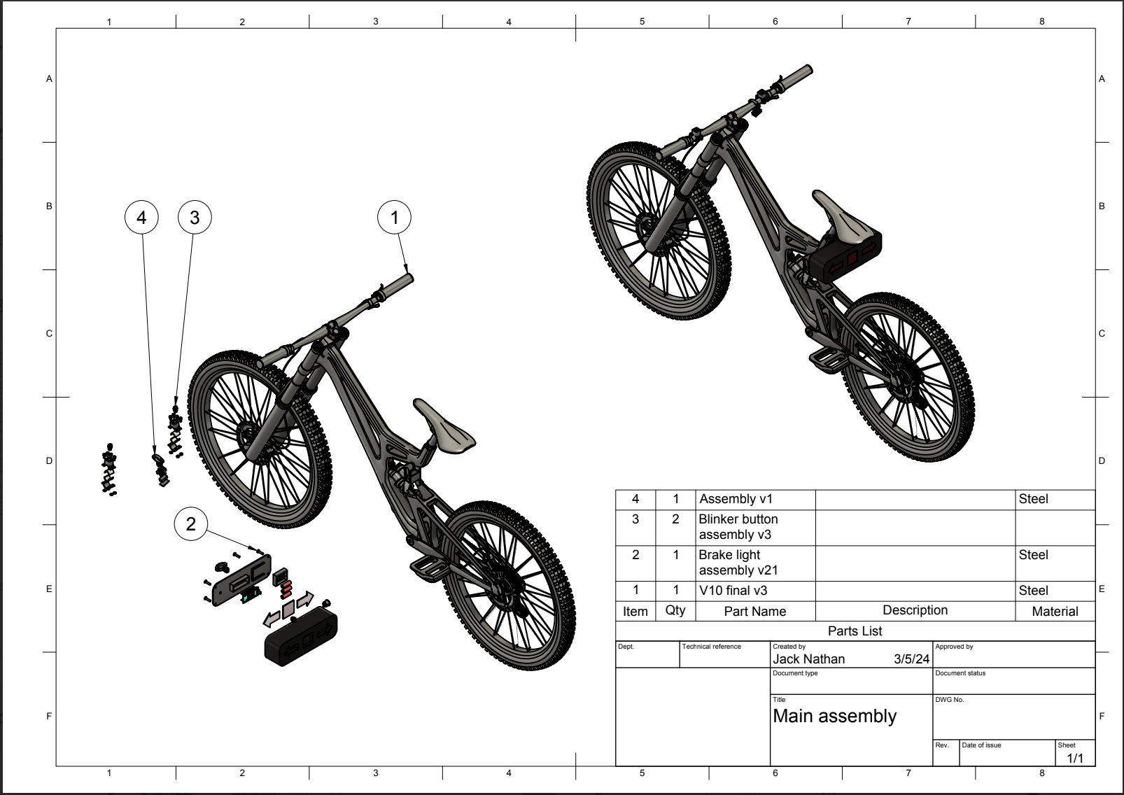
A complete bicycle safety system that projects virtual bike lanes on the ground using lasers while providing turn signals and automatic brake lights. The system mounts under the bike seat with handlebar-mounted turn signal buttons and integrates with the rear brake to trigger brake lights automatically.
The device projects two parallel green laser lines onto the road surface behind the bike, creating a visible "lane" that mimics painted bike lanes. Orange turn signal arrows (left/right) are activated by handlebar buttons, and red brake lights illuminate automatically when the rider applies the rear brake.
Technical Implementation
Control System
The system runs on an Arduino Nano with power from a single battery pack shared across all components. LED strip lights sit behind laser-cut colored acrylic (red for brake, orange for turn signals) in the main housing. Runtime with everything active is approximately 2 hours on one battery.
The turn signal logic is straightforward: press the left handlebar button, the left orange arrow blinks. Press the right button, the right arrow blinks. The buttons connect to Arduino pins (left: 8/9, right: 10/11) and trigger the corresponding LED strips.
Automatic Brake Detection
The brake light system uses a limit switch mounted on the rear brake caliper. When the brake lever pulls the cable, a zip tie threaded through the roller portion of the limit switch triggers it, signaling the Arduino to illuminate the red brake lights.
This was the component I expected to need the most tuning, but it worked perfectly on the first try. No false positives from road vibrations, no missed triggers from light braking. The mechanical simplicity - zip tie pulling on a limit switch - turned out to be more reliable than any electronic sensor would have been.
Laser Lane Projection
Two green line lasers mount to the lower portion of the main housing via 3D-printed brackets. Each laser is held by a single screw that can be loosened to adjust the projection angle and lane width. The lasers run on two 9V batteries wired in parallel, with an on/off switch routed to the handlebars.
We researched eye-safety ratings before selecting the lasers to ensure they met safety standards. The parallel lines project approximately 3 feet apart by default (simulating a standard bike lane), but the swivel mounts allow adjustment for wider spacing if needed.
Mechanical Design & Manufacturing
I designed all components in Fusion 360 and created the technical drawings for documentation. The main housing and all brackets were 3D printed in PLA on the school's printers - no failed prints, which was lucky given the timeline pressure.
The brake and turn signal light covers were laser-cut from colored acrylic at Wando High School's CO2 laser cutter. The acrylic press-fits into slots in the main housing, with LED strips glued behind them.
The entire assembly mounts to the bike via a seat post clamp with a custom screw mount interface. All wiring from the handlebars to the main box runs along the frame, secured with zip ties and electrical tape. Assembly time from individual components to working prototype: about 2.5 hours.
Key Challenges
Mounting Stability & Vibration
The biggest technical challenge was managing vibrations in the main housing while riding. The box needed to be lightweight (to avoid adding too much weight to the bike) but rigid enough to prevent rattling that would misalign the lasers or stress the solder joints.
We solved this through a combination of internal bracing in the 3D-printed design and strategic placement of the battery pack as ballast. The weight distribution helped dampen vibrations rather than amplify them.
Team Dynamics
The harder challenge wasn't technical - it was working with team members who had different motivation levels. This was my first experience leading a long-term hardware project (8 months from concept to final presentation), and I learned that keeping a team on track requires constant communication and breaking work into small, achievable chunks.
I ended up doing most of the work - CAD, drawings, assembly, wiring, code - but that taught me more about project execution than perfectly distributed workload would have.
Water Resistance vs. Manufacturing Reality
Our water resistance test showed moisture intrusion after simulating a heavy rainstorm. Water got in because PLA 3D printing creates layers with microscopic gaps. For a production version, we'd need injection-molded parts with rubber gaskets and proper seals around all openings.
This gap between "prototype that proves the concept" and "product you can sell" was a valuable lesson. Our $120-150 in parts would need to scale down significantly (probably sub-$50 retail) to compete with basic bike lights, which would require different manufacturing entirely.
Testing & Validation
Durability Test
The PLA housing held over 200 lbs before cracking. We stood and jumped on it to simulate worst-case stress - dropping the bike, someone stepping on it, etc. The weak point we worried about (where the backplate screwed into the main shell) held up fine. The system was plenty durable for road use.
Visibility Test
We conducted visibility tests with someone sitting in a car at increasing distances:
Daytime:
- 25ft: Turn signals visible, lasers visible
- 50ft: Turn signals not visible, lasers visible
- 75ft: Nothing visible
Nighttime:
- 25ft: Everything visible
- 50ft: Everything visible
- 75ft: Everything visible
The daytime visibility drop was expected - you can't compete with sunlight when you're running on battery-powered LEDs and low-wattage lasers. The system is designed for night riding, and that's where it performed well.
Brake Switch Reliability
Zero false positives during testing. The limit switch never triggered from bumps or vibrations, only from actual brake lever input. This was the pleasant surprise of the project.
What I Learned
Hardware + Software Integration
This was my first time working with microcontrollers and integrating electronics with mechanical design. Before this, I'd done 3D printing projects, but nothing that combined CAD, embedded code, wiring, and real-world testing. The experience of making something physical that responded to inputs got me hooked on hardware development.
This project directly led to my later drone work - the skills of designing mechanical mounts, managing power distribution, debugging sensor inputs, and thinking through failure modes all carried forward.
Prototype vs. Product
The gap between "it works in the lab" and "it works on the road" is massive. We never actually tested Lane Lasers on real streets at night - we ran out of time, and honestly, it felt like overkill for a class project. But that meant we never validated the core assumption: do drivers actually give cyclists more space when they see laser-projected lanes?
If I were doing this again, that would be the first test. Build a rough prototype, ride it in low-traffic areas at night, measure how cars respond. Everything else is secondary to whether it actually solves the problem.
Regulatory Reality
We didn't research whether laser projection on roads is legal or if it might distract drivers. For a school project, that's acceptable. For a real product, it's a fatal oversight. The lesson: technical feasibility doesn't mean market viability.
Outcome
We presented Lane Lasers to our PLTW capstone engineering class and at a school showcase. The feedback was positive - people liked the idea, and the execution demonstrated that we'd actually built something functional, not just designed it in CAD.
The project came in under budget ($120-150 of a $200 school-funded limit) and met all technical specifications: visible at night, durable enough for road use, water-resistant (not waterproof, but good enough for light rain), and operational for 2+ hours on one battery.
More importantly, it taught me how to take an idea from problem statement to working hardware. The engineering design process we followed - research, ideation, prototyping, testing, iteration - became the framework I still use for technical projects.
If I Rebuilt It Today
Version 2.0 would have:
- Rechargeable battery - USB-C charging instead of swapping 9V batteries
- Better lasers - Higher power (still eye-safe) for better daytime visibility, possibly different color for contrast
- Injection-molded housing - Proper seals, lighter weight, cleaner aesthetics
- Real-world testing - Actually ride it on roads and measure driver behavior changes
I wouldn't add:
- Smartphone app - unnecessary complexity for a safety device that needs to work immediately
- Additional sensors - the limit switch proved mechanical simplicity beats electronic sophistication